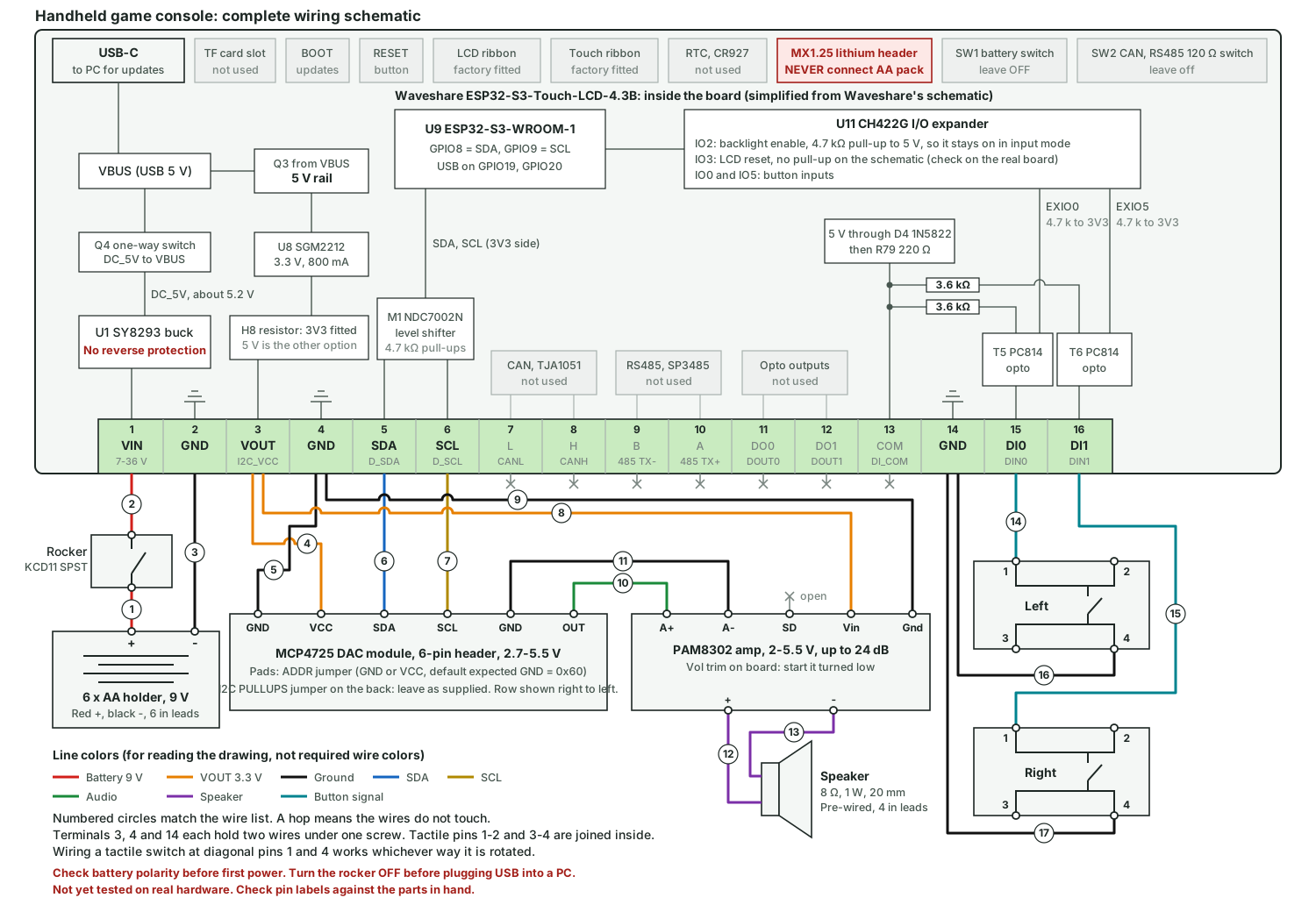
Wiring schematic
The wire list and a port-by-port check are in the
build guide
.
Open the SVG file
.
Handheld game console wiring schematic
Handheld game console: complete wiring schematic
Waveshare ESP32-S3-Touch-LCD-4.3B: inside the board (simplified from Waveshare's schematic)
USB-C
to PC for updates
TF card slot
not used
BOOT
updates
RESET
button
LCD ribbon
factory fitted
Touch ribbon
factory fitted
RTC, CR927
not used
MX1.25 lithium header
NEVER connect AA pack
SW1 battery switch
leave OFF
SW2 CAN, RS485 120 Ω switch
leave off
VBUS (USB 5 V)
Q4 one-way switch
DC_5V to VBUS
DC_5V, about 5.2 V
U1 SY8293 buck
No reverse protection
Q3 from VBUS
5 V rail
U8 SGM2212
3.3 V, 800 mA
H8 resistor: 3V3 fitted
5 V is the other option
U9 ESP32-S3-WROOM-1
GPIO8 = SDA, GPIO9 = SCL
USB on GPIO19, GPIO20
SDA, SCL (3V3 side)
M1 NDC7002N
level shifter
4.7 kΩ pull-ups
CAN, TJA1051
not used
RS485, SP3485
not used
Opto outputs
not used
U11 CH422G I/O expander
IO2: backlight enable, 4.7 kΩ pull-up to 5 V, so it stays on in input mode
IO3: LCD reset, no pull-up on the schematic (check on the real board)
IO0 and IO5: button inputs
5 V through D4 1N5822
then R79 220 Ω
3.6 kΩ
3.6 kΩ
T5 PC814
opto
T6 PC814
opto
EXIO0
4.7 k to 3V3
EXIO5
4.7 k to 3V3
1
2
3
4
5
6
7
8
9
10
11
12
13
14
15
16
VIN
GND
VOUT
GND
SDA
SCL
GND
DI0
DI1
L
H
B
A
DO0
DO1
COM
7-36 V
I2C_VCC
D_SDA
D_SCL
CANL
CANH
485 TX-
485 TX+
DOUT0
DOUT1
DI_COM
DIN0
DIN1
Rocker
KCD11 SPST
+
-
6 x AA holder, 9 V
Red +, black -, 6 in leads
GND
VCC
SDA
SCL
GND
OUT
MCP4725 DAC module, 6-pin header, 2.7-5.5 V
Pads: ADDR jumper (GND or VCC, default expected GND = 0x60)
I2C PULLUPS jumper on the back: leave as supplied. Row shown right to left.
A+
A-
SD
Vin
Gnd
PAM8302 amp, 2-5.5 V, up to 24 dB
Vol trim on board: start it turned low
+
-
open
Speaker
8 Ω, 1 W, 20 mm
Pre-wired, 4 in leads
Left
Right
1
2
3
4
1
2
3
4
1
2
3
4
5
6
7
8
9
10
11
12
13
14
15
16
17
Line colors (for reading the drawing, not required wire colors)
Battery 9 V
VOUT 3.3 V
Ground
SDA
SCL
Audio
Speaker
Button signal
Numbered circles match the wire list. A hop means the wires do not touch.
Terminals 3, 4 and 14 each hold two wires under one screw. Tactile pins 1-2 and 3-4 are joined inside.
Wiring a tactile switch at diagonal pins 1 and 4 works whichever way it is rotated.
Check battery polarity before first power. Turn the rocker OFF before plugging USB into a PC.
Not yet tested on real hardware. Check pin labels against the parts in hand.