Handheld Build Guide
A two-button handheld game console, designed for a family build. This covers what it is, why it's designed this way, what to buy and print, and how it goes together.
Nothing here has run on real hardware yet. The software has been compiled and tested in a simulator, and the shell has been checked on screen and in the slicer. Bench-test the electronics, and measure the real board, before printing the shells.
Overview
The handheld is landscape, with a 4.3" screen in the middle and one button on each side. It runs five small games, written in C++, on a Waveshare ESP32-S3 display board. Six regular AA batteries power it, and a USB-C cable loads new software from a PC. The shell is 3D printed on a Bambu Lab A1 mini and snaps together with no screws or glue.
| Item | Value |
|---|---|
| Size (wide x tall x deep) | 6.69 x 3.31 x 1.42 in (170 x 84 x 36 mm). The depth depends on a board thickness I had to estimate. |
| Screen | 4.3", 800 x 480, RGB interface. Games draw at 400 x 240 and each pixel is doubled. |
| Controls | Left and right buttons. Holding both for one second returns to the game menu. |
| Power | 6 x AA in series, about 9 V, into the board's 7-36 V input |
| Sound | Square-wave beeps through an I2C converter, an amplifier and a 0.79 in speaker |
| Games | Peel or Skip, Banana Catch, Monkey Dash, Tower Stack, Quick Draw (two players) |

Where things stand
| Area | Status | What that means |
|---|---|---|
| Games | Tested in simulator | Autopilots played them on a PC, and a person play-tested some of them. PC speed says nothing about board speed. |
| Board software | Compiles | Screen, buttons and sound code all build. None of it has run on a board. |
| Shell | Checked on screen | All part pairs show no overlap, and every piece slices with supports off and no warnings. Nothing has been printed. |
| Parts | Ordering | The parts were placed in an Amazon cart for checkout. |
Design decisions
| Decision | Why | What was rejected |
|---|---|---|
| All-in-one ESP32-S3 board with a 4.3" screen | It needs little wiring, and its 8 MB PSRAM has room for full frame buffers. | Arduino Uno: 2 KB RAM can't hold a frame. Pico 2 with a 4" SPI screen: about 25 FPS at best, and more wiring. 5" board: its width pushed the buttons within 0.15 in of the shell edge. |
| Type B version of the 4.3" board | It has two isolated digital inputs for the buttons, without needing a spare GPIO. | Plain 4.3" board: no digital inputs. |
| Two buttons, with no home button | The goal was a simple layout and easy assembly. Holding both for a second reaches the menu, and an on-screen bar shows it's working. | A third button: it adds a part and a hole, and has no confirmed input. |
| Replaceable AA batteries | Chosen over a rechargeable battery. Six cells make 9 V, inside the board's input range. | The board's lithium connector: it has a charger on it, so it's unsafe for AA cells. Stacked AA holders: at 1.10 in thick they don't fit. |
| Sound over I2C | The board has no audio and no confirmed free GPIO, but it does have an I2C terminal, so nothing inside the board gets tapped. | I2S amplifier: it needs three GPIOs, which would mean tapping the unused SD slot. |
| 170 x 84 mm body | It fits the A1 mini's 180 x 180 mm bed and keeps the space around the screen tight. | Nintendo Switch width (239 mm): it doesn't fit the bed and has too much empty space. |
| Snap fits, with a separate inner plate | No fasteners are needed. As a separate flat piece, the plate avoids a long span printed in mid-air, so nothing needs supports. | Plate molded into the back shell: a long unsupported bridge. |
| One C++ codebase for simulator and board | Games are written once against a small interface, then compiled to WebAssembly for the browser and to ESP32 for the board. | Separate versions, which would drift apart. |
Please check first
These are the places I'm least sure of, roughly in order of how much trouble they could cause. Board details come from my reading of Waveshare's schematic, which is worth a second look from someone who knows electronics.
| Question | Why it matters | How to check, or what to do instead |
|---|---|---|
| Does the screen stay on with the CH422G pins set to input? | The CH422G sets IO0-7 all to input or all to output together. The schematic shows a 4.7 k pull-up from the backlight enable (EXIO2) to 5 V, so the backlight should stay on. LCD reset (EXIO3) shows no pull-up, so it relies on the panel or the chip to stay high. | Watch the screen on the first bench test. If it blanks or resets, use an I2C GPIO expander such as a PCF8574 for the buttons. |
| Is the sound too hot? | The amp has up to 24 dB of gain (about 16 times). The code's DAC_SWING of 900 sends about ±0.73 V, far more than enough to clip at 3.3 V. A clipped square wave puts about 1.4 W and 0.4 A into the 1 W speaker, all from the 3.3 V regulator. No code has been changed for this yet. | Start with the amp's Vol trim low. Try DAC_SWING near 100, which gives about 0.2 W at full gain. Measure the 3.3 V rail during a tone. |
| Can the I2C terminal's VOUT power the amplifier? | VOUT comes from the board's SGM2212 regulator (800 mA, 3.3 V as supplied), which also runs the ESP32. Its real headroom and heat haven't been measured. | Check that the 3.3 V rail holds, and how warm U8 gets, during long tones. |
| Is 0x60 free, and is it the converter's address? | The bus also carries the expander, touch controller and clock. Waveshare reserves 0x20-0x27, 0x30-0x3F and 0x5D, and the clock uses 0x51. Some MCP4725 modules ship with a different address, and this one has an ADDR solder jumper. | Run an I2C scan. The address is DAC_ADDRESS in the sketch. |
| Is it safe to connect USB with the batteries on? | Not as far as I can tell. Q4 lets the battery-side 5 V (about 5.2 V by its feedback resistors) reach VBUS, and USB VBUS appears to share that net, so it could feed back into the PC's port. | Turn the rocker off before plugging in USB, and confirm this reading of the schematic. Waveshare also notes the screen draws close to 550 mA, more than a weak PC port may supply, so use a strong port. |
| How long will the batteries last? | Current draw hasn't been measured. A 7 V minimum across 6 cells is about 1.17 V per cell, so it may shut off before the cells are fully used. | Measure the draw at 9 V, then test down to the point where it browns out. |
| Is 30 FPS stable, with no picture drift? | Heavy PSRAM use while the screen refreshes can cause drift on this chip. Doubling a frame writes about 23 MB/s while the screen reads about 32 MB/s. | Watch the speed report over USB. Settings are 16 MHz pixel clock, which works out to about 39 Hz refresh, with an 8000-pixel bounce buffer. |
| Do the board's real dimensions match? | Board thickness (0.55 in is my estimate), USB-C position (the top middle is my guess), screen centering, terminal heights, and BOOT and RESET locations are all unconfirmed. | Measure, then edit the values at the top of handheld.scad. The board sits tight against the inner plate, so tall connectors on its back could collide. |
Battery safety: connect the AA pack only to the 7-36 V input. Never connect it to the lithium battery connector, because the charger on that connector could try to charge AA cells and make them leak or burst. VIN has a surge clamp but no series diode on the schematic, so a reversed battery could damage the board. Check polarity with a meter before first power.
Parts manifest
To buy
| Part | Used | Pack | Price | Notes |
|---|---|---|---|---|
| Waveshare ESP32-S3 4.3" Touch LCD, type B | 1 | 1 | $42.99 | No case. Confirm the board says 4.3B, because the listing shows no SKU (27848). About $4.32 delivery. |
| 12 x 12 x 7.3 mm tactile switch | 2 | 25 | $9.78 | Sits behind each button cap |
| Flat 6 x AA holder, 90 x 58 x 15 mm | 1 | 5 | $13.73 | 9 V, with 6 in leads |
| KCD11 SPST rocker switch | 1 | 5 | $6.49 | A listing photo shows a 15.5 x 10.5 mm face, 20 mm tall. Check its body against the 15 x 10 mm cutout. |
| MCP4725 12-bit I2C DAC module | 1 | 4 | $9.99 | Sound signal |
| PAM8302 2.5 W amplifier | 1 | 1 | $5.49 | Low stock when checked |
| Speaker, 1 W 8 ohm, 20 x 4 mm | 1 | 2 | $6.74 | Pre-wired. Low stock when checked. |
| 22 AWG stranded silicone wire, 6 colors | A little | 10 ft each | $12.79 |
Total $108.00 before tax and delivery. Prices are from when the cart was filled. Already on hand or at home: soldering kit, 6 AA batteries, a USB-C data cable, and PLA filament.
To print
| Piece | Count | Size (in) | Est. print time, each | File |
|---|---|---|---|---|
| Front shell | 1 | 6.69 x 3.31 x 0.63 | 3 h 56 min | front_shell.stl |
| Back shell, with battery compartment | 1 | 6.69 x 3.31 x 1.09 | 6 h 20 min | back_shell.stl |
| Inner plate | 1 | 3.94 x 2.68 x 0.06 | 47 min | inner_plate.stl |
| Battery door | 1 | 3.84 x 2.63 x 0.35 | 1 h 32 min | battery_door.stl |
| Button cap | 2 | 0.71 round x 0.28 | 7 min | button_cap.stl |
| Switch bracket | 2 | 0.63 x 1.28 x 0.20 | 9 min | switch_bracket.stl |
Times are Bambu Studio estimates at its 0.20 mm standard setting in PLA, with supports off. Each file is already flat for printing. Print one bracket and test it on a post before committing to a shell, because the slicer can't judge how the snaps flex.
Wiring
This takes 17 wires and 18 solder joints, none of them on the main board, which connects through its 3.5 mm screw terminals. Check the terminal labels against the real board.
Schematic
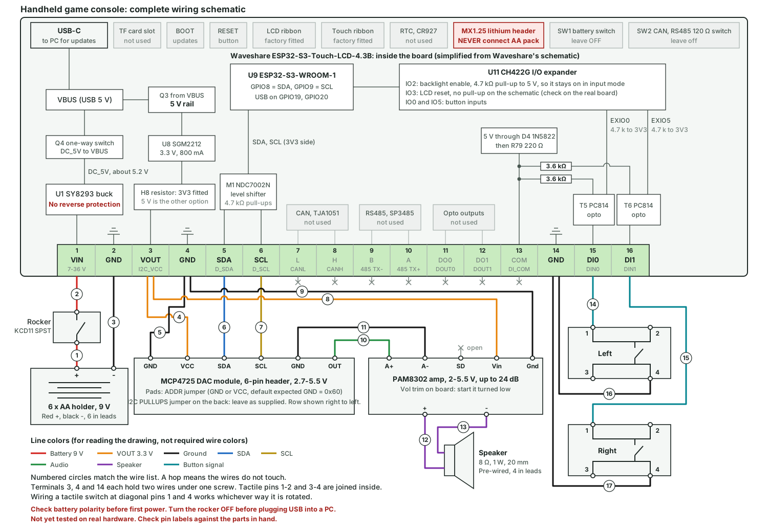
Wire list
| Wire | From | To | Notes |
|---|---|---|---|
| 1 | Battery + (red) | Rocker, one terminal | Either terminal; solder or use a spade connector |
| 2 | Rocker, other terminal | Terminal 1, VIN | Rocker is in series on the positive side |
| 3 | Battery - (black) | Terminal 2, GND | |
| 4 | Terminal 3, VOUT | MCP4725 VCC | 3.3 V as supplied |
| 5 | Terminal 4, GND | MCP4725 GND, next to VCC | |
| 6 | Terminal 5, SDA | MCP4725 SDA | ESP32 GPIO8 through the level shifter, 400 kHz |
| 7 | Terminal 6, SCL | MCP4725 SCL | ESP32 GPIO9 through the level shifter |
| 8 | Terminal 3, VOUT | PAM8302 Vin | Second wire under the same screw as wire 4 |
| 9 | Terminal 4, GND | PAM8302 Gnd | Second wire under the same screw as wire 5 |
| 10 | MCP4725 OUT | PAM8302 A+ | Keep short, and twist with wire 11 |
| 11 | MCP4725 GND, next to OUT | PAM8302 A- | Makes the amp's differential input single-ended |
| 12 | PAM8302 + | Speaker lead | Neither output goes to ground. With one speaker, polarity doesn't matter. |
| 13 | PAM8302 - | Other speaker lead | |
| 14 | Terminal 15, DI0 | Left switch, pin 1 | EXIO0 on the CH422G |
| 15 | Terminal 16, DI1 | Right switch, pin 1 | EXIO5 on the CH422G |
| 16 | Terminal 14, GND | Left switch, pin 4 | Diagonal from pin 1 |
| 17 | Terminal 14, GND | Right switch, pin 4 | Second wire under the same screw as wire 16 |
How a button press registers: with COM left empty, closing a switch pulls current from the board's own 5 V through D4, 220 Ω, 3.6 kΩ and the opto's LED to GND, about 0.9 mA. The opto then pulls its CH422G input low. The code treats whichever level it reads at startup as "not pressed", so don't hold a button at power-on.
Every port on every part
| Part | Used | Left empty | Checked against |
|---|---|---|---|
| Main board, 16-way terminal | 1 VIN, 2 GND, 3 VOUT, 4 GND, 5 SDA, 6 SCL, 14 GND, 15 DI0, 16 DI1 | 7 L, 8 H, 9 B, 10 A, 11 DO0, 12 DO1, 13 COM | Schematic connector P1, plus Waveshare's labeled board photo |
| Main board, other | USB-C, BOOT and RESET when updating | Lithium header (never use), SW1 (leave off), CR927 socket, TF slot, SW2 (leave off) | Schematic, Waveshare product page |
| MCP4725 module | OUT, GND, SCL, SDA, VCC, GND: all six | ADDR and I2C PULLUPS jumpers stay as supplied | Amazon listing photos |
| PAM8302 module | A+, A-, Vin, Gnd, +, - | SD, which Adafruit's matching design pulls up on the module. Vol trim is a screw, not a wire. | Amazon listing photos, Adafruit's pinout guide |
| Speaker | 2 leads | Amazon listing | |
| Tactile switches, each | Pins 1 and 4 | Pins 2 and 3. Pins 1-2 and 3-4 are joined inside. | Amazon listing circuit diagram. Confirm with a meter. |
| Rocker | 2 terminals, either way round | Amazon listing photo and specs (KCD1-11, SPST) | |
| 6 x AA holder | Red and black leads | Amazon listing photo. Confirm polarity with a meter. |
The HiLetgo amp's listing doesn't publish its own schematic, so the SD pull-up is taken from the near-identical Adafruit design. If the amp stays silent, check that SD reads high.
Software
The game code is in handheld/game, the browser simulator is in handheld/sim, and the board code is handheld/firmware/handheld/handheld.ino. The sketch builds against the Arduino esp32 package 3.0.7, with no other libraries beyond Wire. It uses about 327 KB of flash, plus 211 KB of RAM mostly for the game's frame.
From the handheld folder, with the rocker off and the board plugged in over USB-C:
powershell -ExecutionPolicy Bypass -File .\update_handheld.ps1
Add -CompileOnly to build without uploading. If the PC doesn't see the board, try another cable, then hold BOOT while plugging in. Open a serial monitor at 115200 to see frame rate, frame time and raw input pins once a second. A healthy result is about 30 FPS with a frame time under 33 ms.
Assembly
Bench test first
Before printing the shells, upload the software to the bare board and confirm the screen stays on. Wire the buttons, then the sound parts, then the batteries, testing after each. Then measure the board and update the CAD if needed.
Step 1: Drop in the button caps
Turn the front shell face down and drop a cap into each round hole from the inside. The wider rim stops it falling through.

Step 2: Snap on the switch brackets
Press a tactile switch into each bracket, plunger toward the cap, and solder on its wires. Press each bracket over its two posts until both barbs click.

Step 3: Set the board in place
Connect the button wires to DI0 and DI1, with both return wires under the GND screw beside them, and leave COM empty. Lower the board, screen first, into the four corner guides.

Step 4: Close the shell
Press the rocker switch into its slot and wire it in. Connect the sound parts and seat the speaker in its mount. Pass the battery wires through the small hole in the compartment wall. Lay the inner plate on the back of the board with its corner nubs facing the batteries. Then press the back shell on until all six arms click into their windows. To open it again, push a small pin into the windows.

Step 5: Add the batteries and door
Put the holder in the compartment and connect its wires. Hook the door's tongue under the edge of the back panel, then press the other end down until the latch clicks. To open it, pull at the finger notch.

Finished


USB-C access
The cable plugs directly into the board through a slot in the shell's top edge, so updates don't require opening anything. Switch the batteries off first. The slot's position is a guess until the real board is measured.
Inside view
A slice through the middle, with the front at the bottom. From bottom to top: board and screen (green), inner plate, battery pack (blue), and door. At each end, the cap (light gray) presses the switch (dark), which is held in the bracket (orange).

